Handlebar Switch, Right - Removal/Installation - CBF 1000A DIY
This DIY describes how to remove the right handlebar switch on a 2007 CBF1000A Honda motorcycle
and is applicable for 2006 to 2009 models and maybe later models.
Error Symptoms
- You suddenly discover that both headlights are off while engine is running!
- You turn on the high-beam switch on the left handlebar, and both lights still remains off!
- You pull the overtake button on the left handlebar and high-beam turns on.
These are clear indications that the starter switch in the right handlebar switch unit is
faulty and does not re-establish correct voltage to the low beam headligt and the high beam
relay after having been pushed to start the engine.
The fault may typically only happen very rarely, but with time more and more often. Sometimes the
headlight can be turned on again if you gently pull outwards and wriggles on the starter button.
General Description
The right handlebar switch unit comprices starter switch, hazard on/off switch and engine kill
switch. The unit is delivered from Honda as one sparepart including all required cabeling and is
normally not servicable.
When the starter switch is pressed, 12 Volt is applied to the starter via the starter relay, and
- to minimize load on the battery while starting - the 12 Volt supply to the low beam and to the
high beam relay is at the same time switched off. When the starter switch is released again, the
head light voltage is reapplied.
One failure mode of the starter switch is hence that the headlights are not turned on again when
the switch is released. You will still be able to turn on the high beam with the overtaking switch
in the left handlebar switch, as this switch is connected via a different part of the circut.
Time and Tools
This is a reasonably easy DIY task. It involves some tricky manipulation of the gas cable
wires as there is not much slack to play with. A first timer may spend 3-5 hours doing it,
an experienced might do it in 1-2 hours. It involves removal of the the upper left and right cowls
and the front center cowl compricing the head light assembly.
Tools, spareparts and consumables needed:
- Allen keys (4, 5 mm).
- Fork spanners (8, 10, 14 mm).
- Screw driver (pz 1).
- Pliers.
- New right handlebar switch unit, Honda part number 35130-MFA-D02.
- Silicone grease.
- Copper grease.
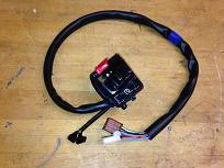
The right handlebar switch assembly (image below left) is delivered from Honda as one unit
compricing all cables and connectors. The unit is not considered serviceable
by Honda, and I tend to aggree with Honda on this.
The electrical contacts are not directly accible from neither ouside nor from inside, so it is quite
difficult to inspect and clean the electrical terminals inside the switch. I hence recommend to
replace the entire switch assembly, although it is quite expencive - I had to bleed arround 1000
Danish kr. for it, i.e. arround 135 EUR!
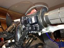
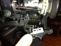
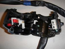
The image above right shows the switch unit flipped open so you can see the inside. Notice
how the starter switch is mounted behind the hazard switch.
It is indeed possible to unmount and open the starter switch to get access to clean the switch
terminals inside the switch, but it is a somewhat tricky job, and it is difficult to say
whether or not a successfull and reliable repair can be done. The following description is
hence showing how to replace the entire switch unit.
For those who want to try to save money, I describe at the end of the article
how the starter switch can be dismantled, cleaned and assemled again. Be aware that this
is however a quite difficult job, and may not result in a 100% reliable switch and could hence be
a safety issue.
Removal Procedure
From the following pictures you may see yhat I did not remove the cowls until after
I had removed the switch assembly from the handlebar. You may do it in whatever sequence you prefer.
Also notice that my bike has heated grips installed, so a wire for the right grip is visible in some of the
images. This has no significant influence on this task however.
1.0 Remove upper cowls, inner pannels and front center cowl - details.
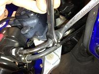
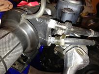
2.0 Release the 10 mm contra nut on the gas cable adjuster on the upper cable and adjust the
8 mm nut to make the gas cable as slack as possible (image below left). Be sure not to twist the gas
cable while doing this. Screw out the 14 mm cable nut from the switch unit at the lower gas cable,
and release the 14 mm lock nut on the upper cable. (image below right).
3.0 Unscrew the two pz1 screws from the bottom of the switch unit. They may be tight and
a little difficult to brake loose, so use a good screw driver for this. Notice that the two
screws have different lengts and that the shorter screw is placed towards the front of the
bike.
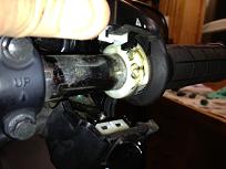
The switch unit can now be flipped open as shown in the image below left. The two halfes
will still hang together with the wires connecting to the kill switch in the upper half.
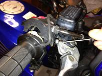
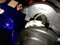
It is now possible to push the lower wire sideways and off the white ring to get some
extra slack so you can slide the round cylinder on the end of the wire sideways out and
remove the cable (image below left and middle).
The upper wire can now easily be removed also (image below right).
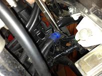
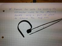
5.0 Remove the cable clamp on the steering stem at the blue marking on the switch unit cable.
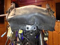
6.0 Remove the rubber sheet covering the instrument cluster. Here you will now see the
switch unit connectors.
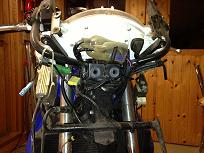
7.0 Disconnect the two switch unit connectors (white and brown).
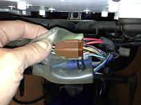
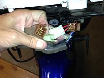
Tie a 1 meter long piece of string on the cable at the connectors end, and then pull out
the switch unit cable while letting the string take the place of the cable.
This string will be used during reassembly to pull the new switch unit
cable into place, thereby making sure that the new cable gets exactly the same routing as
the old cable had.
8.0 Installation procedure is same as removal procedure in reversed order. Be sure to
route and mount the switch unit cable excactly as he old cable was.
When the switch unit cable and the gas cables have been installed, carefully inspect
that the cables are routed correctly and behaves well when the steering handle is turned
fully left and right.
If you want to save the cost of a new swich unit you can try to repair the switch as
described in the following. I can however not give ...
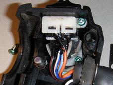
9.0 Remove the 3 1pz screws marked with green arrows in the middle image below
(click on the image to see the large version) and remove the cover plate and the cable
bracket. Then remove the 1pz screw holding the starter switch.
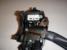
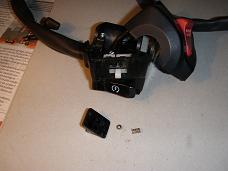
10.0 Pull the hazard swith button off using a screw driver as a lever to release it.
Be carefull not to loose the spring and metal ball in the process (image below left).
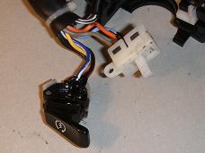
Remove the hazard switch and next the starter switch using a screw driver to brake them
loose from small groves in the plasitc casing (image below middle).
Inspect the starter switch and notice exactly how the spring and the push button are
mounted on the metal stud.
The starter switch can now be opened by pullling out on the white ends and releasing the
snap lock tabs on the top plate with the wires (image below right).
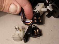
You now have access to the metal contact points and can scrape them clean with a sharp
knife blade and smear them with some silicone grease.
Notice that on the image above right I had wrongly placed the spring onto the metal tab
before I took the picture. This is misleading, because on reassembly you must first mount
the button on tab, then mount the spring and finally mount the top plate while holding
and squizeing the button into correct position. With a last push on the top plate it will
snap-lock into position. All this is quite tricky, so good luck - especially if you have
large bulky fingers!
Finished.
The thread titled
Starter switch failure causes loss of head lights! on the www.cbf1000.com
forum may be used for comments and feed back, or you may mail directly to me (mail address is on the
front page).
Front Page
© Copyright 2013 FireBladerDk - last updated 2013-10-14


