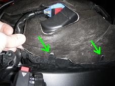
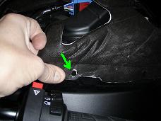
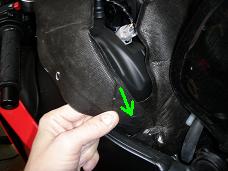
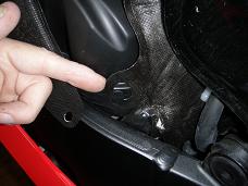
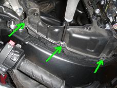
Release the air cleaner cover from the plastic tabs (green arrows below middle) and remove the cover.
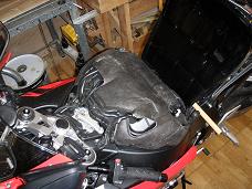
This Do It Yourself (DIY) article describes how to remove and reinstall the
air cleaner housing on a 2008 CBR1000RR Honda Fireblade motorcycle.
This job is normally done as part of the valve
clearance inspection.
This is a reasonably easy DIY task. It involves many steps but none of them are dificult, so take your time and keep track of where you are in the process. A first timer may spend 4-8 hours on it, an experienced may do it in about 3 hours.
Tools and Parts needed: qwe
Front Page - Other DIY Articles
1 Place the bike on the side stand or on a rear wheel lifter.
3 Remove the Air Cleaner as described in the following:
3.1 Remove the Air Cleaner Cover:
Release the air cleaner cover from the plastic tabs (green arrows below middle)
and remove the cover.


3.2 Disonnect Connectors for:
- Left handlebar switch, 10 pin blue (below middle and right).
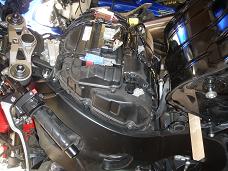
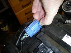
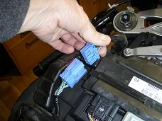
- Right handlebar switch, 8 pin white (below left).
- Ignition switch, 2 pin brown (below middle).
- Immobilizer receiver, 4 pin black (below right).
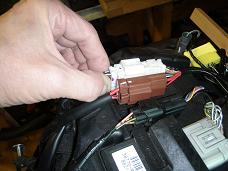
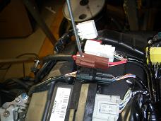
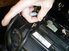
3.3 Detatch ECM Setting Plate:
- Detach the blue left handlebar switch connector from its mounting bracket (below left).
- Remove the two screws holding the plastic bracket (ECM Setting Plate) which fixates
the Engine Control Module (below middle and right).
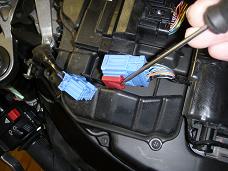
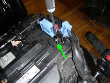
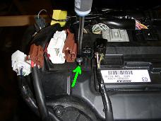
3.4 Clearing ECM and Harness Away:
In the following be carefull not to stress or bend the harness too much. Further
notice that the ECM connectores are not disconnected at all, as we do
not want to have any problems with bad connections afterwards.
- Pull the setting plate with connectors and the harness up and rearwards.
Also pull the ECM - still attached to the harness - up and rearwards. Then
tie them up with a piese of string (below left to right).
- Pull the front part of connectors and harness forward and tie them up with a
string.
You will now have easy access to the air cleaner housing upper cover (below right).
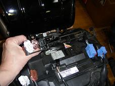
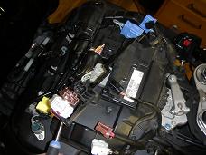
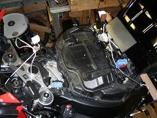
Keep it clean from now on! We will now be opening
to the inside of the air cleaner with direct access to the inside of the engine.
- Use a vacuum cleaner and brush to clean away any loose dirt particles on the
outside of the air cleaner.
Be very carefull not to drop anything into the engine, and cover the area with
a towel when you take a pause or leave the bike.
3.5 Removing the Air Cleaner Housing Upper Cover:
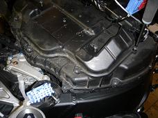
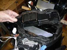
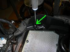
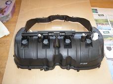
- Unscrew the six screws holding the air cleaner housing upper cover (below left)
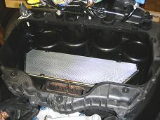
and remove the cover (below middle). You are now able to see the inside of the
air cleaner. Take a moment to enjoy the elegant design with the fuel
injectors hanging directly over each of the four air funnels (below right).
3.6 Remove the Air Cleaner Element:
- Loosen the two screws (one in each side) holding the air cleaner element in place
and remove the element, while taking care not to drop anything into one of the
four air funnels (below left).
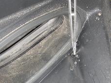
- You will now be able to see the lower compartment of the air cleaner housing with
a RAM air inlet in both sides. You will most likely find all sorts of debris which
has found its way through the inlets, so clean it carefully scraping off debris and
vacuum clean thoroughly. Also make sure the small drain hole in each side is free
from drebris. I had to use a pair of tweezers to get the small gravel particles
out (below right).
- Gently blow the filter inside the air cleaner element clean using compressed air from the
throttle body side (i.e. from the upper side). If the filter is damaged or excessively
dirty, it is time to order a replacement air cleaner element.
3.7 Releave Fuel Pressure:
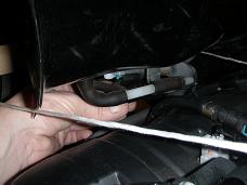
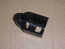
- Remove the quick connect fitting cover from the fuel pump end of the fuel line
(below left). It is a little black plastic cover as shown below middle, and is
hidden behind all the other tubes and hoses, so I could not get a good picture
of it in it's correct position, so you must use your eyes to see and your
fingers to feel here :-). Reach in with left hand when standing on the right side
of the bike and simply peel it off.
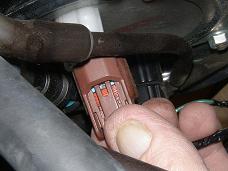
- Disconnect the fuel pump 2 pin brown connector (below right). Reach in from
the left side of the bike and squeze hard on the connector and it can be pulled
off quite easy.
Now we will start the engine to let it use up any fuel still standing under
pressure in the fuel line:
- Reconnect the right side connectors (white, brown and black) which were
disconnected in previous section 3.2.
- Reconnect the battery
- Turn ignition on (notice that there is no sound from the fuel pump
as we have diconnected it).
- Start the engine and let it idle a few moments untill it stalls.
- Turn ignition off.
- Disconnect battery.
- Disconnect right side connectors.
3.8 Disconnect Fuel Line:
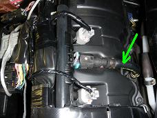
The flexible fuel line comming up from under the tank is connected to the
upper fuel rail joint with a so-called quick connect fitting as
shown in the image below left (click on the image to see further details).
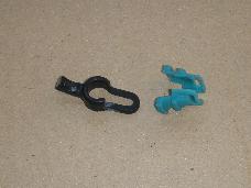
A small piece of rubber - called a rubber cap - acts as a locking device,
which ensures that the joint will not accidentially spring open. A small piece
of cyan collored plastic - called a retainer - has two locking pawls
which graps into two holes in the connector.
- Clean all the components in this area with soft cloths and compressed air.
Gasoline molecules are small and may leek through even very small scratches in
the critical areas of the quick connect fitting, so be very carefull not to
make scratches or leave dirt on these parts.
- Place a cloth under the joint, as a few ml can be expected to spill out.
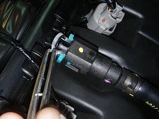
- Pull and release the rubber cap from the joint, while carefully using your
eyes to see exactly how it was placed. I used a pair of twezers as shown in
the image below middle for this job.
- With your fingers only, squeeze the retainer taps to unlock the powls and
gently pull the connector off the fuel joint tube. If it has dificulty
comming off, work it back and forth untill it comes off. Some fuel will drip
out and should be collected in the cloth you placed under the joint.
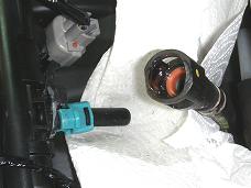
- Remove the retainer and the rubber cap from the joint tube and bag them
(below left).
- Place a small plastic bag over the end of the fuel line connector, so it is
well protected against mechanical damage and dirt (below right).
- Disconnect the grey 2 pin connector for the Input Air Temperature (IAT)
sensor (below middle).
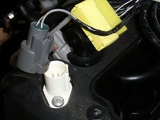
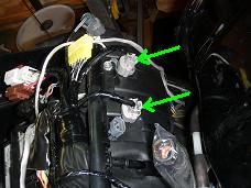
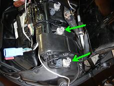
- Disconnect the four grey 2 pin connectors for the secondary fuel injectors
(above right and below left)
- Tie the ECM and harness up and out of the way as shown below right.
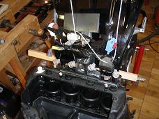
3.9 Remove Air Cleaner Middle Housing:
- Remove the 8 screws holding the middle housing of the air cleaner (below left).
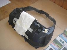
- Remove the air cleaner middle housing and attach a soft protecive cover over
the fuel joint (below middle and right).
3.10 Remove Air Funnels:
- On both sides, loosen the air funnel screws and remove the air funnel (images below).
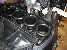
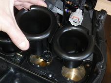
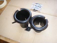
3.11 Remove Lower Part of Air Cleaner Housing :
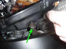
- Disconnect the Manifold Absolute Pressure (MAP) sensor 3 pin blue connector
at the rear right corner of the air cleaner lower housing (below left).
- Lift the front end of the lower housing a few cm up and disconnect the cranckcase
breather hose (below middle and right). I used a pair of pliers to squeze on the
clamp and wriggle the clamp a couple of cm down.
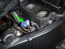
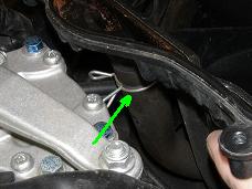
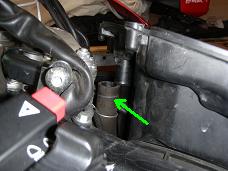
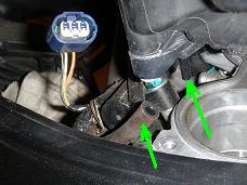
- Lift the lower housing a few cm up in the rear right corner and disconnect
the vacuum hose (below left) and the Pulsed Secondary Air Injection (PAIR)
air suction hose (below middle and right)
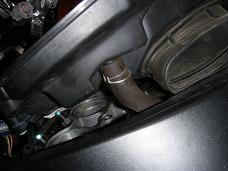
- Remove the air cleaner lower housing (below left to right).
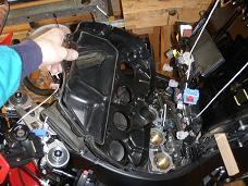
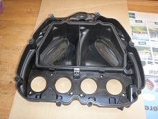
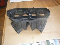
The image below presents an overview of the engine top with the air cleaner removed.
- Place a cloth over the air intakes and clean the entire area thoroughly.
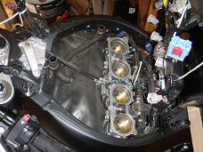
Installation procedure is same as removal procedure in reversed order and with exceptions as described in the referenced DIY articles and in the overview here below.
4.1 Preparing for Fuel Pressure Test:
- Remove the cloth over the air intakes.
- Place the lower air cleaner housing over the engine and bring it down partly into position.
- Press the cranck case breather hose onto the front middle stud. and place the clamp
correctly. This is slightly difficult due to limited space.
- Remount the PAIR air suction hose and its clamp.
- Remount the vacuum hose on the rear right bottom stud.
- Reconnect the 3 pin blue MAP sensor connector.
- Remount the air funnels.
- Remount the middle housing and tighten the 8 screws to 0.8 Nm.
- Connect the 4 secondary injectors and the IAT sensor 2 pin grey connector.
- Connect the quick connect fitting to the secondary fuel rail:
 According to the Honda Shop Manual you should always use a new retainer, but I really do not
see the need for this. The retainer seems to be pretty robust and it is not part of the
sealing mechanism. It's only purpose is to keep the parts locked together, so I reused
the old one.
If the rubber cap is damaged it should off course be replaced.
 Insert the retainer into the black connector on the fuel line. Place the rubber cap
on the black pipe on the secondary fuel rail. Make sure to turn it as shown on the
image at left.
4.2 Fuel Pressure Tests:
- Reconnect the battery.
- Turn on the ignition and the engine stop switch. You should now hear the fuel
pump operate for about 2 seconds.
- Inspect for fuel leaks using your eyes and your sense of smell.
- Repeat this a couple of times more.
- Disconnect the battery again (we do not want to work on the bike while having
power on the harness).
4.3 Remaining Components Below the Tank:
- Install the air cleaner element.
- Install the air cleaner upper cover (6 screws).
- Install ECM and setting plate (2 screws).
- Reconnect the connectors: 4 pin black, 2 pin brown, 8 pin white and 10 pin blue.
- Install air cleaner cover (the soft fabric).
7 Reconnect the Battery
8 Remount Seat and Side Covers.
Finished.
Front Page - Other DIY Articles
You are invited to participate with review, questions and discussion via this - link to come - thread on www.fireblades.org or this - link to come - thread on www.1000rr.net.
See also:
How to DIY (warnings, tips, tools,
methods, ... etc.)
First Year
with my Fireblade
Superbikes on the Road: BMW S1000RR versus
Honda CBR1000RR Fireblade
Front Page - Other DIY Articles
© Copyright 2012 FireBladerDk 2012-04-08. Last update 2013-02-24