
This Do It Yourself (DIY) article describes how to make Valve Clearance Inspection on a 2008 CBR1000RR Honda Fireblade motorcycle. This inspection must be carried out every 24.000 km according to Hondas mainteneance schedule.
Valve clearance is the size of the small gap between cam and valvestem when the
valve is fully closed.
- A too large gap results is clicking noises and reduced engine performance.
- A too small gap results in poor engine performance and hot gasses burning valve
and valve seat.
|
OBS: A too small gap condition will NOT give any warning signs before
it is too late! You will not be able to hear it and the engine will be damaged
and require expencive cylinder head repair. It is my impression that many professional workshops do not take this seriously. They will charge you for a valve inspection, but in fact they just listen for clicking noises. |
In case any of the valve gaps are ouside the specifed range, you will have to make valve clearance adjustment. This is done by exchanging shims and is subject of another DIY article to be written when I have been through this task myself. It is however very similar to how it is done on a Honda CBF1000 and you can find a DIY article on this here: Valve Clearance Adjustment - CBF1000A
This is a very comprehensive DIY task where you strip quite a lot of components off your bike and where some of the steps require accuracy and patience. A first timer may spend several days on it, an experienced may do it in one day.
Tools and Parts needed:
Be systematic in the way you work: Place removed items on a table so you can easily pick them up in reversed sequence during assembly. Bag screws, clips and other small items clearly marked with what they are used for. Maintain check lists showing how far you have come, e.g. on print-outs from this DIY.
1 Check Engine Idle Speed with warm engine. It must be 1.200 +/- 100 RPM.
2 Place the bike in upright position so you have easy access to both
sides and to the front.
You may do the job using the side stand only, but upright is easier, and if you can
lift the bike that will be even better.
3 Remove the middle cowl from both sides.
5 Remove the air cleaner housing.

6 Remove the PAIR control solenoid valve.

7 Remove the direct ignition coils and spark plugs.

8 Remove the cylinder head cover.

Important: While the cylinder head cover is off, be very very carefull not to drop any dirt into the cylinder head. Cleanliness is of utmost importence!
9 Inspect Valve Clearence as Described in the Following:
9.1 Remove the timing hole cap and the O-ring.
My bike is equipped with crash bungs, so first job was to remove the 5 screws holding the
crash bung onto the timing the cap on the right side of the engine(below left). Then I
reinserted two of the screws and used a long screw driver as leverage to release the
timing hole cap (below middel).


9.2 Turn the cranck shaft to allign the intake cam sprocket correctly:
The bolt head in the middle of the timing cap hole is the end of the cranck
shaft (image above right). Place a top wrench on the bolt and turn it clockwise untill the
T||F timing mark on the cranck shaft is alligned with the
timing mark on the right cranck case cover as shown on the image below left.
Check that the punch mark on the inside of the intake cam sprocket is now alligned
with the top edge of the cylider head as shown on the image below middle. Also check using
a small mirror that the IN timing mark on the outside
of the intake cam sprocket is alligned with the top edge of the cylider head as shown on
the image below right. Notice how I used a small dentist mirror to see the mark on the
outside.
If theese marks are not alligned as shown, you must turn the cranck
shaft exactly one rotation (360 degrees) clockwise, and then recheck allignment.


To make sure this initial allignment is correct, use the mirror to check that the
EX timing mark on the outside of the exhaust cam sprocket
is alligned with the top edge of the cylider head (no image shown of this). The exhaust cam
sprocket is the leftmost sprocket in the small image here above (middle).
The input cam shaft has now been put into position for inspection of the input valves clearances in cylinder 1 and cylinder 3 (cylinder numbers are counted from the left side of the bike, i.e. cylider 1 is the leftmost cylinder and cylinder 4 is the rightmost).
9.3 STEP 1:
Check valve clearance for input valves I1L, I1R, I3L and I3R as shown on the
drawing below.
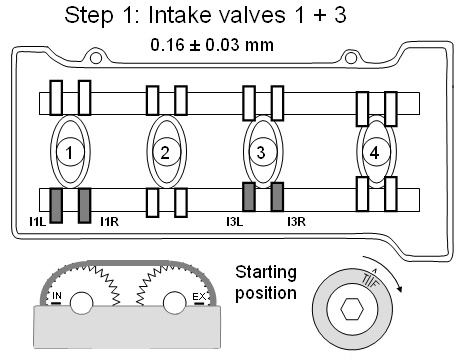
Insert a 0.10 mm feeler gauge into the gap at valve I1L (Input 1 Left).
Now assuming the 0.10 mm blade can pass into the gap, try with progressivly thicker blades,
untill you can no longer get it in. Then note down carefully the thickest blade you could get
in, and the thinnest blade you could not get in, e.g. like "I1L: +0.10, -0.15". Then do the
check again, to be sure you did it right.
The input gap specification is 0.16 +/- 0.03 mm.
You may have to combine two feeler blades to get a certain thickness, e.g. 0.10 + 0.15 to get 0.25 mm.
You can probably combine blades to achieve thickness in steps of 0.05 mm in the relevant interval, so how is it really possible to measure with the tight tollerances specified by Honda? Well - it is something that you have to feel with your fingers. Depending on the gap size you may find that the thickest possible blade inserts very easily, i.e. with little force. If so, note the result with a tripple plus sign like "+++0.30". If it inserts with medium force, note it as "++0.30", and if it only inserts with difficulty write "+0.30". In this way you will know the actual gap size with a slightly improved resolution.
If you have a micrometer, it is a good idea to calibrate each blade: Dip a blade in engine oil and insert it in the gap of the micrometer. Turn the micrometer to the nominal thickness of the blade and then pull out the blade. This way you will know which force is the right one to use for that particular blade.
Now check the I1R, I3L and I3R valves in the same way and note down the results.
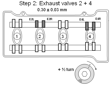
9.4 STEP 2:
Turn the cranck shaft 180 degrees clockwise (i.e. 1/2 turn).


Check valve clearance for output valves E2L, E2R, E4L and E4R as shown on the drawing below and note down the results. The exhaust gap specification is 0.30 +/- 0.03 mm, so start with a 0.25 mm feeler blade.
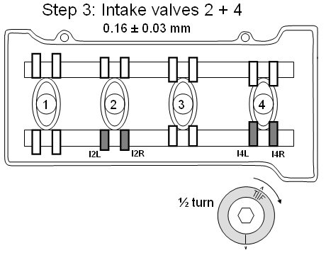
9.5 STEP 3:
Turn the cranck shaft 180 degrees clockwise (i.e. 1/2 turn).
Check valve clearance for input valves I2L, I2R, I4L and I4R as shown on the
drawing below and note down the results.
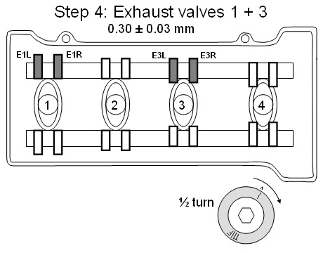
9.6 STEP 4:
Turn the cranck shaft 180 degrees clockwise (i.e. 1/2 turn).
Check valve clearance for output valves E1L, E1R, E3L and E3R as shown on the drawing below and note down the results.
9.7 Result Evaluation:
The table below shows my measurement results (in hundreds of a milimeter).
| Valve | Blade insertion | Actual gap | Allowed gap | Comment |
| I1L | ++15 -20 | 15 | 13 .. 19 | OK |
| I1R | ++15 -20 | 15 | 13 .. 19 | OK |
| I2L | ++15 -20 | 15 | 13 .. 19 | OK |
| I2R | ++15 -20 | 15 | 13 .. 19 | OK |
| I3L | ++15 -20 | 15 | 13 .. 19 | OK |
| I3R | ++15 -20 | 15 | 13 .. 19 | OK |
| I4L | ++15 -20 | 15 | 13 .. 19 | OK |
| I4R | ++15 -20 | 15 | 13 .. 19 | OK |
| E1L | ++30 -35 | 30 | 27 .. 33 | OK |
| E1R | ++30 -35 | 30 | 27 .. 33 | OK |
| E2L | ++30 -35 | 30 | 27 .. 33 | OK |
| E2R | +30 -35 | 28 | 27 .. 33 | OK |
| E3L | ++30 -35 | 30 | 27 .. 33 | OK |
| E3R | ++30 -35 | 30 | 27 .. 33 | OK |
| E4L | +30 -35 | 28 | 27 .. 33 | OK |
| E4R | +++25 -30 | 27 | 27 .. 33 | OK - but on limit |
Symbols:
| "+++" | low pressure to insert | add 2 to blade thickness (a completely non-scientific value!) |
| "++" | normal pressure to insert | use blade thickness |
| "+" | high pressure to insert | subtract 2 from blade thickness |
| "-" | can not be inserted |
Here is a blank table for your measurement results.
Assuming all the results are within specification, you can start assembling the bike.
If any of the gaps are outside specifications, you must remove the camshaft for inspection and replace the relevant shims with thicker or thinner shims as appropriate. Or - you might put the bike on a trailer and take it to your local mechanic and let him do that slightly more complicated job.
9.8 Valve Clearance Adjustment.
As all valve measurements were inside specified ranges on my bike, I have not yet done
this job myself and has hence not been able to write a DIY. Fortunately bross from
(www.cbf1000.com) has done the job on his CBF1000 which
has an almost identical engine, and he has prepared this excellent
Valve Clearance Adjustment DIY Article and given me
permission to integrate it in this site.
Thanks bross !!
Installation procedure is same as removal procedure in reversed order and with exceptions as described in the referenced DIY articles and here below.
10.1 Remount Timing hole cap:
Inspect the O-ring on the timing hole cap and replace it with a new one if it is not in good condition.
Apply engine oil to the O-ring and grease on the timing hole cap threads. Then remount the cap, tightening it to 18 Nm (1.8 kgfm, 13 lbfft).
10.2 Inspect and install the cylinder head cover.
10.3 Inspect and install the spark plugs and ignition coils.
10.4 Inspect and install the PAIR Control Solenoid Valve.
10.5 Install the air cleaner housing.
10.6 Lower the Fuel Tank.
10.7 Remount the Top Shelter.
10.8 Reconnect the Battery.
10.9 Remount Seat and Side Covers.
Finished.
You are invited to participate with review, questions and discussion via this - link to come - thread on www.fireblades.org or this - link to come - thread on www.1000rr.net.
See also:
How to DIY (warnings, tips, tools,
methods, ... etc.)
First Year
with my Fireblade
Superbikes on the Road: BMW S1000RR versus
Honda CBR1000RR Fireblade
© Copyright 2012 FireBladerDk Last updated 2013-10-21.
