
This DIY describes how to adjust valve clearance on a 2007 CBF1000A Honda motorcycle and is (as far as I know) applicable for 2006 to 2010 models. This adjustment must be made if a valve is found to be outside specified range during Valve Clearance Inspection.
Bross (from www.cbf1000.com) has prepared an excellent DIY and given me permission to integrate it in this site. Hence pictures and most of the text in this article is his work. Thanks bross !!
Like the valve clearance inspection this is not an easy DIY task. Please read about this in the Time and Tools section of the Valve Clearance Inspection article.
Tools, spareparts and consumables needed:
In addition to what was listed for "Valve Clearance Inspection" the following is needed:
Notice that the special cam chain tensioner with Honda part number 07ZMG-MCAA400 is definitely not required and is hence not in the above list.
When doing DIY work you will undoubdtedly at some point run into troubles like e.g. stuck bolts or other things which will not come apart. Instead of just spinning out of control using the big hammer, have a look in the " Undoing Stuck Bolts, Nuts and other Metal Parts" section.
Dismantle and inspect as described in the Valve Clearance Inspection DIY and the related articles.
Please have the service manual to refer to as this is just my photo record and shouldn't be trusted as how to do it. Basically, you break it, you bought it and all those other disclaimers.
You may click on the small pictures to see a larger version with more details.
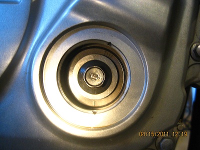
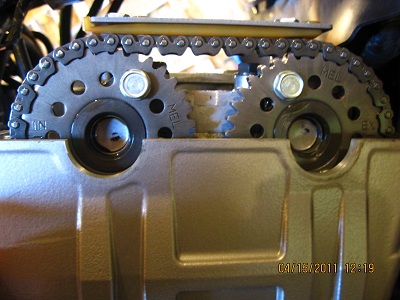
First step is to align the cams so the index mark is at the 6 o'clock position and the cams are aligned with "IN" and "EX" aligned with the head (images below left and right).
Remove the upper cam chain guide (below left) and tie up the cam chain so it doesn't fall into the motor (below right).
Next remove the cam chain tensioner. Do not bother buying the Honda tool (07ZMG-MCAA400) as it does not fit the CBF tensioner. It is too long to engage or lock the tensioner in the retracted position. You can simply remove the 2 tensioner bolts and remove the tensioner from the engine (below left). Installation is simply using a thin flat blade screwdriver to wind and hold the tensioner in the retracted position while you insert and snug the 2 bolts.
There are 3 camshaft holders that need to be unbolted, a Left (Camshaft Holder B), Right (Camshaft Holder A) and a narrow holder called "Camshaft Holder C". The bolts should be loosened in a crisscross pattern a little at a time to avoid cracking or damaging the holder! (see image below middle). The holders are labelled with an "L" for left, "R" for right so you can't mix them up. The holders also have all the bolt holes numbered in the proper tightening sequence. There are 3 different bolts used; long, short, and those with a sealing washer. Basically the inner bolts on the left and right holder use a sealing washer, while the exhaust side use the long bolts and the intake side use the short bolts.
Be very careful removing the inside bolts with the sealing washers (below right). I dropped one into the motor and because they're copper you can't retrieve with a magnetic tool. I used a dab of 'Goop" on the end of the magnetic tool to fish out the washer. You've been warned.
Exhaust, Intake and inside bolts (below left). Bolt tightening sequence numbers, you can also see the "L" and "R" markings (below middle). .
The camshaft holders were on snugly and I couldn't move them by hand, I ended up using a screw driver, very gingerly to pry slightly up on the holders (above right and below left). What you don't see in the pictures is a folded rag I had between the screwdriver and the head so I didn't damage the gasket sealing surface. It didn't take much to loosen the holders.
Check the condition and make sure the o-rings are seated in the camshaft holders, look for any scoring where the cams ride (below middle and right).
Notice: If the mileage is high, it might be a good idea to do some further inspection steps on camshaft and camshaft holders. See the Honda Shop Manual for details on this.
Ready to pull the cams (below left). Sorry for the blurry pic (below middle), but you may have to tilt the intake cam slightly to remove the cam chain. Lift the cam from the left side and you can then slide the cam chain off.
Intake cam out and showing the buckets and the magnetic tool I used to pull the
bucket out of the head (above right and below left).
Bucket and shim (below middle). Another magnetic tool to retrieve the shim from the
bucket (below right).
The magnetic tools (below middle). Shim removed (below right).
New shim installed (below left). Measuring the original shim (below middle). Both cams out (below right).
Cams are labeled so you can't mix them up (below left). Buckets galore (below middle) .
Use the following formula to calculate the new shim thickness:
A = (B - C) + D
where:
A: new shim thickness
B: recorded valve clearance
C: specified valve clearance
D: old shim thickness
Once you have replaced all the out of spec shims it's time to re-install the cams. Just reverse the process of taking the cams out but make sure you align the "IN" and "EX" marks with the edge of the head again. This ensures the timing is correct. I installed the exhaust cam first and it was easy to align the "EX" mark as I had lots of play in the cam chain but it took a few tries to juggle with the chain and rotate the Intake cam until I had the "IN" mark lined up properly.
Inspect the O-rings in the cam shaft holders and smear them with clean engine
oil.
Also lubricate all journals of the cyclinder head and camshaft holders generously
with clean engine oil so they will have an oil film to float on when the engine is
started. The Honda Shop Manual actually specifies using molybdenum oil solution for
this, but to mee that seems like overkill.
Install the camshaft holders and finger tighten all the bolts, then start slowly tightening the bolts in the numbered sequence a little at a time until you have torqued them all to the required 9 lbf-ft (12 Nm, 1.2 kgm) . My lb-ft torque wrench is not accurate at that little torque so I used my lbf-in small wrench instead and torqued to 108 lbf-in.
Notice: The cam shaft holder may break if not tightened in proper crisscross pattern.
Install the cam chain tensioner. I used a thin flat blade screw driver to wind the tensioner clockwise to retract the tensioner (below left), then holding the tensioner body and the screwdriver to keep it retracted re-install the tensioner into the engine (below middle) and get the bolts finger tight before letting go of the screwdriver (below right). Now tighten the bolts on the tensioner.
Remount the upper cam chain guide - torque 9 lbf-ft (12 Nm, 1.2 kgm).
Recheck the valve clearances before installing the cam cover.
Follow instructions in the Valve Clearance Inspection DIY and the related articles.
The thread Valve Clearance Adjustment on www.cbf1000.com may be used for comments and feed back, or you may mail directly to me (mail address is on the front page) .
Finished.
© Copyright 2011 FireBladerDk - Last updated 2011-04-27