Valve Clearance Inspection - CBF 1000A DIY
This DIY describes how to inspect valve clearance on a 2007 CBF1000A Honda motorcycle
and is applicable for 2006 to 2010 models. This inspection must be done every 24.000 km
(16.000 miles). At the same time it is a good idea to replace spark plugs and radiator
coolant, plus to do a few extra things, now that you have full access to do it.
Most car engines have hydralic valve lifters which automatically adjusts the valve
clearance, but on the CBF valve clearances are set using shims of selected thickness,
and over many thousand kilometers the clearance may increase or decrease depending
on how hard the engine is working. If the clearances become too large, ticking noises will be
generated. If the clearances become too small, the valves will not close properly, so valves
and valve seats will be damaged by hot gasses and compression will drop. In the later case
there will be no warning of malfunction before severe damage occurs.
It is rumored that some professional mechanics just listen to the engine, and if no valve
clicking is heard, the inspection is finished!!! Hence you'ed better use a mechanic you trust,
as a correct inspection (where you actually measure the valve clearances) is a time
consuming work.
Time and Tools
This is not an easy DIY task. It involves quite many individual steps, some of which are
a bit tricky and which - if not done with care - may damage components. Especially the
high tension spark plug leads, coils and caps are prone to be damaged if handled too hard.
A first timer may spend 15 hours or more doing it, an experienced might do it in 5 hours.
If you are a beginner in DIY, better have an experienced friend giving a hand.
Tools, spareparts and consumables needed:
- CBF1000A tool kit which was supplied with the bike.
- Allen keys (4, 5 mm).
- Socket spanners (7, 8, 10, 12, 14, 17 mm).
- Screw driver (pz 1, 2).
- Pliers.
- Plastic hammer.
- Gauge blades (0.10, 0.15, 0.20, 0.25, 0.30, 0.35, 0.40 mm).
- Spark plugs: NGK: CR8EH-9 or DENSO: U24FER9.
- Copper washer for coolant drain plug.
- Coolant: 3 liters high quality ethylene glycol antifreeze containing corrosion inhibitors,
1:1 mixture with destilled water.
- Sealer: silicone RTV sealant (RTV = Room Temperature Vulcanisation).
- Oil: normal engine oil.
- Greese: e.g. silicone grease.
A spark plug alternative is Iridium NGK CR8EHIX-9 for longer life and, reputedly better
performance, but I have no personal experience with these. I also have my doubts and concerns,
because there is an old saying that "if something works, then don't mess with it". And
I anyways recommend to use new spark plugs at each valve clearance inspection, so longer life
is not of much use.
Tips
When doing DIY work you will undoubdtedly at some point run into troubles like e.g. stuck
bolts or other things which will not come apart. Instead of just spinning out of control
using the big hammer, have a look in the "
Undoing Stuck Bolts, Nuts and other Metal Parts" section.
Dismantling Procedure
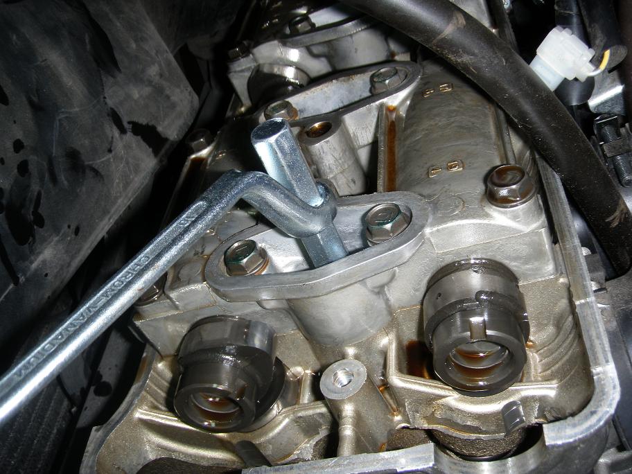
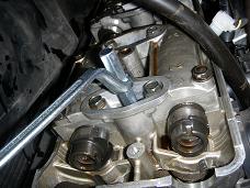
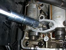
1.0 Remove the valve cover - details
Important: While the valve cover is off, be very very
carefull not to drop any dirt into the cylinder head. Cleanliness is of utmost
importence!
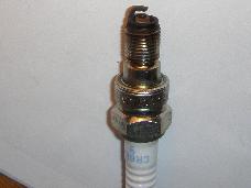
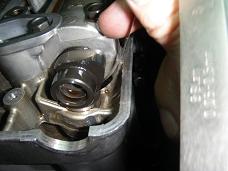
2.0 Remove the four spark plugs using the supplied tool.
You will find that they are burried quite deep down in the cylinder head! The supplied tool
has a small rubber ring which will grab around the plug, so the plug can be lifted up. Be
sure not to drop any dirt into the cylinder or into the cylinder head.
Inspect each spark plug as you get it up. The deposits on the spark plug will tell you how
well the engine is running with respect to temperature, mixture ratio and oil leakage. See
NGK's descriptions.
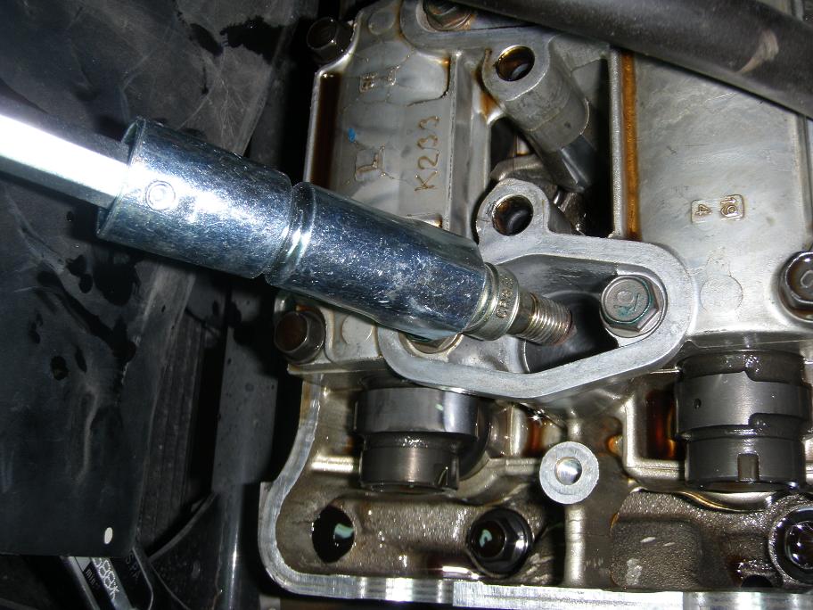
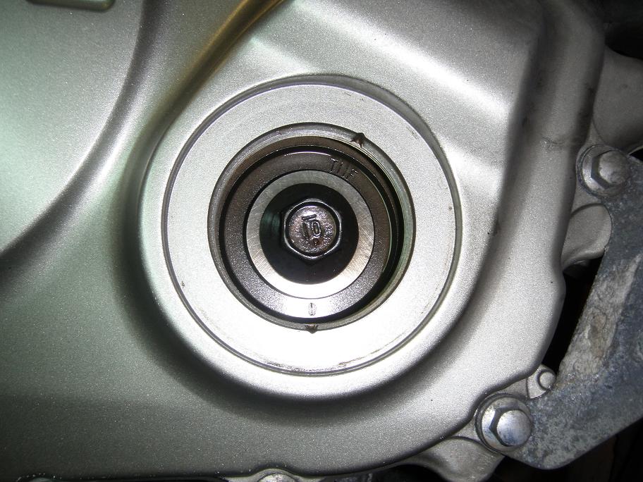
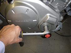
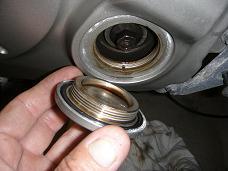
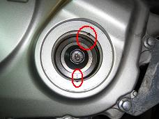
3.0 Remove timing hole cap and O-ring.
Valve Check Procedure
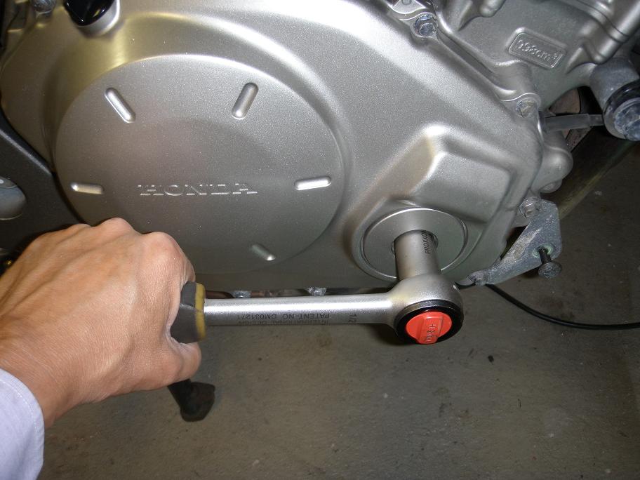
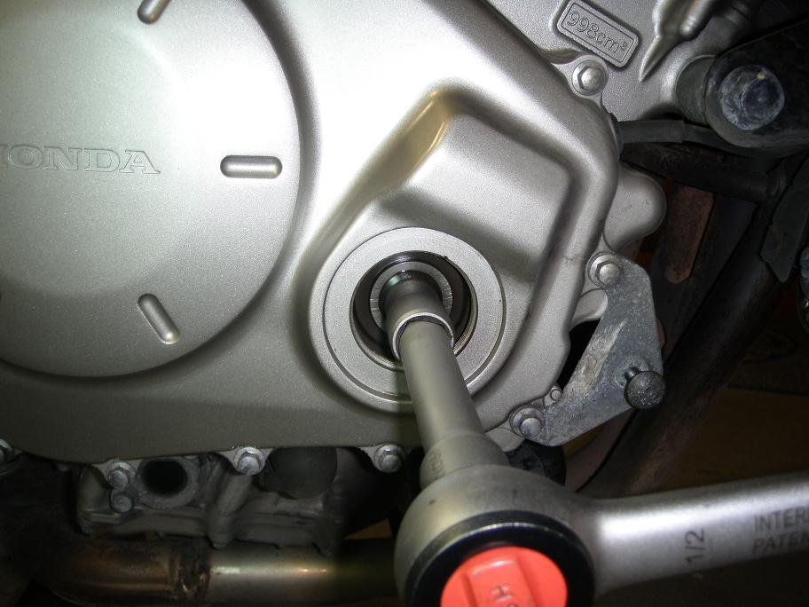
4.0 There are a total of 16 valves to check, 8 input valves and 8 output valves. They are
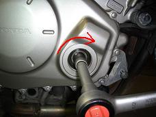
checked in 4 steps, each with the cranck shaft turned to specific positions. To reach the
required positions, use a socket spanner to turn the cranck shaft slowly clockwise (and only
clockwise!) until it reaches the correct position as indicated on the picture in each of the
following sections 4.1 to 4.4 .
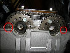
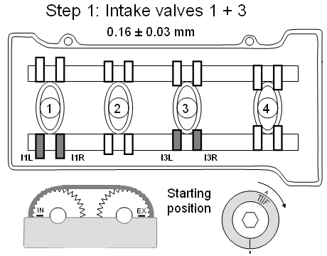
4.1 Step 1:
Turn the crank shaft untill the "TIIF" mark is alligned with the notch in the one
o'clock position and the "I" mark points straight down in six o'clock position. Then check
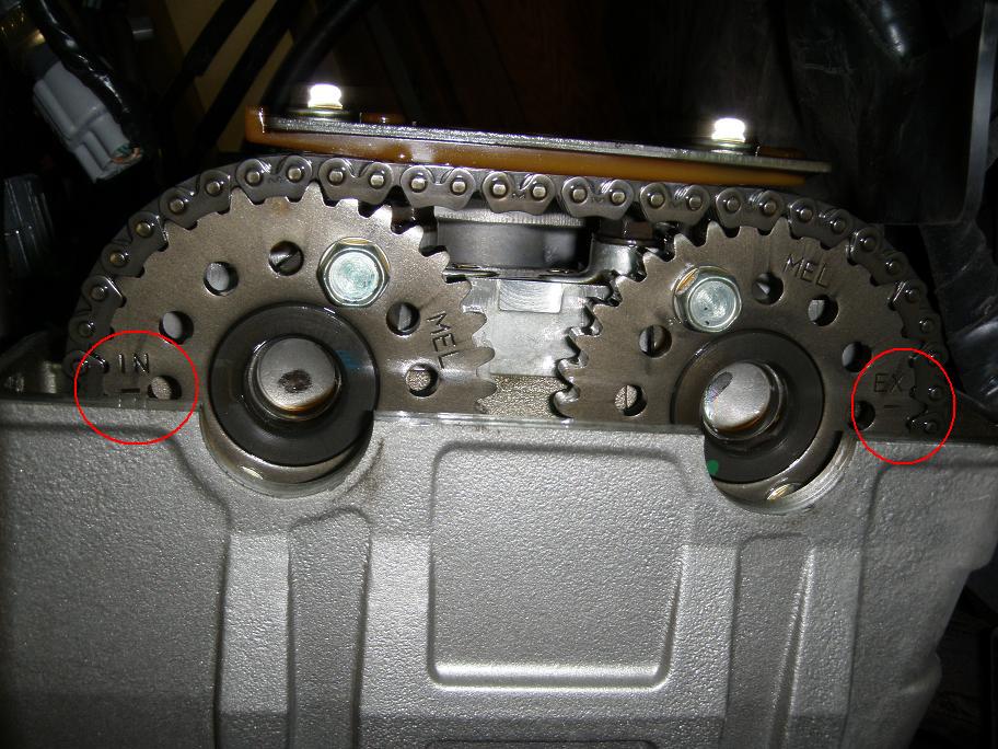
if the "IN" and "EX" markings on the cam sprockets are alligned as shown in picture and
drawing here below.
If the "IN" and "EX" markings are turning upside down and placed near the middle, you must
turn the crank shaft one full turn extra to get them in th correct position.
You are now ready to do valve clearance measurements in input valves I1L, I1R, I3L and I3R as
shown on the drawing below.
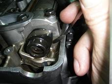
Insert a 0.10 mm feeler gauge into the gap at valve I1L (Input 1 Left).
If you did not know why it is called a feeler gauge, now is the time for you to find out,
because you will now have to train your fingers with the feeler gauge on this I1L valve gap
untill you blindfolded can feel wether or not the blade can slide into the gap.
The reason you must be able to do it like that is that most of the other valve positions are
place so you can not see them directly. You litterally have to feel it.
Furthermore - to be able to get into the narrow space I had to dismantle my set of feeler gauge
blades, so as only to have individual blades and I also had to make a curved bending on the end
of each blade, as clearly seen on the first image below.
Now assuming the 0.10 mm blade can pass into the gap try with progressivly thicker blades,
untill you can no longer get it in. Then note down carefully the thickest blade you could get
in, and the thinnest blade you could not get in, e.g. like "I1L: +0.10, -0.15". The do the check
again, to be sure you did it right.
You may have to combine two feeler blades to get a certain thickness, e.g. 0.10 + 0.15 to get
0.25 mm.
You can probably combine blades to achieve thickness in steps of 0.05 mm in the relevant
interval, so how is it really possible to measure with the tight tollerances specified by
Honda? Well - again it is something that you have to feel. Depending on the gap size
you may find that the thickest possible blade inserts very easily, i.e. with little force. If
so, note the result with a tripple plus sign like "+++0.30". If it inserts with medium force,
note it as "++0.30", and if only inserts with difficulty write "+0.30". In this way you will
know the actual gap size with a slightly improved resolution.
Now check the I1R, I3L and I3R valves in the same way and note down the results.
4.2 Step 2:
Turn the crank shaft clockwise 1/2 turn (180 degrees) so the "I" mark points straight up.
Check exhaust valves E2L, E2R, E4L and E4R and note down the results. The exhaust gap
specification is 0.32 +/- 0.03 mm, so start with a 0.25 mm feeler blade.
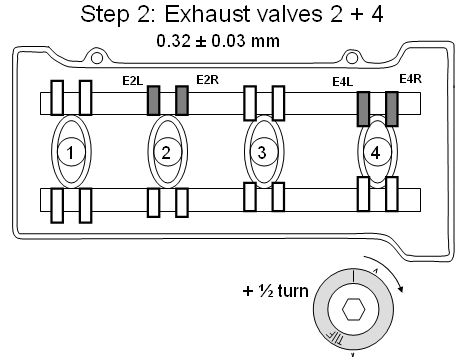
Comment: You might wonder why the exhaust specification calls for a larger gap than for
the intake valves. This is most likely because the exhaust valves have to operate at higher
temperatures and over a larger temperature range than the intake valves, and must hence have
a larger nominal gap to ensure that there will actually be a gap under all operating
conditions. The intake valves are cooled by the intake air, which due to the pressure drop
(suction) in the input manifold may be 5 to 10 degree centigrades lower that the surrounding
air temperature. The exhaust valves are heated be the hot exhaust gasses, causing the valve
stems to expand in length, thus reducing the gap.
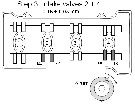
4.3 Step 3:
Turn the crank shaft clockwise 1/2 turn (180 degrees) so the "I" mark points straight down.
Check input valves I2L, I2R, I4L and I4R and note down the results. The input gap
specification is 0.16 +/- 0.03 mm, so start with a 0.1 mm feeler blade.
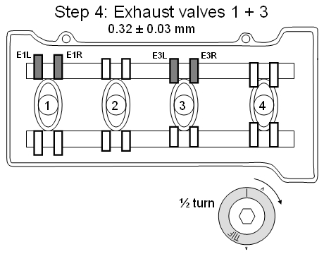
4.4 Step 4:
Turn the crank shaft clockwise 1/2 turn (180 degrees) so the "I" mark points straight up.
Check exhaust valves E1L, E1R, E3L and E3R and note down the results. The exhaust gap
specification is 0.32 +/- 0.03 mm, so start with a 0.25 mm feeler blade.
5.0 Result evaluation.
The table below shows my measurement results (in hundreds of a milimeter) taken at 27.000
km.
| Valve |
Blade insertion |
Actual gap |
Allowed gap |
Comment |
| I1L |
+++15 -20 |
17 |
13 .. 19 |
OK |
| I1R |
+++15 -20 |
17 |
13 .. 19 |
OK |
| I2L |
+++15 -20 |
17 |
13 .. 19 |
OK |
| I2R |
+++15 -20 |
17 |
13 .. 19 |
OK |
| I3L |
+++15 -20 |
17 |
13 .. 19 |
OK |
| I3R |
+++15 -20 |
17 |
13 .. 19 |
OK |
| I4L |
+++15 -20 |
17 |
13 .. 19 |
OK |
| I4R |
+++15 -20 |
17 |
13 .. 19 |
OK |
| E1L |
++30 -35 |
30 |
29 .. 35 |
OK |
| E1R |
++30 -35 |
30 |
29 .. 35 |
OK |
| E2L |
+35 -40 |
33 |
29 .. 35 |
OK |
| E2R |
+35 -40 |
33 |
29 .. 35 |
OK |
| E3L |
++30 -35 |
30 |
29 .. 35 |
OK |
| E3R |
++30 -35 |
30 |
29 .. 35 |
OK |
| E4L |
++30 -35 |
30 |
29 .. 35 |
OK |
| E4R |
++30 -35 |
30 |
29 .. 35 |
OK |
Symbols:
| "+++" |
low pressure to insert |
add 2 to blade thickness (a completely non-scientific value!) |
| "++" |
normal pressure to insert |
use blade thickness |
| "+" |
high pressure to insert |
subtract 2 from blade thickness |
| "-" |
can not be inserted |
|
If you have a micrometer, it is a good idea to calibrate each blade: Dip a blade in
engine oil and insert it in the gap of the micrometer. Turn the micrometer to the nominal
thickness of the blade and then pull out the blade. This way you will know which force is
the right one to use for that particular blade.
Here is a blank table for your
measurement results.
Assuming all the results are within specification, you can start assembling the bike
again.
If any of the gaps are outside specifications, you must remove the camshaft for inspection
and replace the relevant shims with thicker or thinner shims as appropriate. Or - you might
put the bike on a trailer and take it to your local mechanic and let him do that slightly
more complicated job.
5.1 Valve Clearance Adjustment.
As all valve measurements were inside specified ranges on my bike (at 27.000km) I have
not yet done this job myself and has hence not been able to write a DIY. Fortunately
- for all of us - bross from (www.cbf1000.com) has done the
job and he has prepared this excellent Valve Clearance
Adjustment DIY Article and given me permission to integrate it in this site.
Thanks bross !!
Assembly Procedure
6.0 Smear the timing hole cap O-ring with a little engine oil and the thread with some
silicone greese and tighten the cap to 18 NM (1.8 kgfm, 13 lbfft).
7.0 Mount 4 new spark plugs.
Most likely you will not have to revisit the engine top for the next 24.000 kms, so don't
bother reusing the old plugs. You just risk having to dig into the engine top again sooner.
Spark plug gap must be 0.80 - 0.90 mm. Adjust by bending them if required.
When mounting the plugs, you may smear the thread with a small amount of copper
grease or mount it dry as done in the factory as far as I know (see the discussion about
this further below). And - most importantly - make sure the threads engage correctly without
using anything more the finger force. Then tighten - still only with small force - untill
the compression type sealing washer contacts the cylinder head surface. You can feel the
resistance against rotation increasing sharply when this happens.
If you are reusing the old plugs, be sure to clean the threads first and tighten to
16 Nm (1.6 kgfm, 12 lbfft), and slightly less if you used grease.
If you are installing new plugs, the washer must be compressed correctly. This is
done by turning the plug for about an extra half turn (180 degrees). The torque required
for this will be stable around 16 Nm, maybe slightly higher, while the washer is compressing.
Stop turning when the torque starts increaseing steeply beyond 16 Nm (slightly less if you
used grease).
8.0 Install the valve cover - details
Tip: Whenever possible, leave bolts, nuts and screws in their original positions
while you continue work. Then you have them in the right place for reassembly.
Tip: Remember to smear the threads on bolts and screws with copper grease before you
remount them. Then you will have an easy task, next time you have to disassemble. Exception
is the timing hole cap where the threads are smeared with silicone grease.
Greasing the Spark Plug Threads or Not
You may chose to dry mount the spark plugs or you may chose to apply a small amount of
copper grease to the threads. There are different oppinions out there about what's best, so
you must chose for yourself. Anyway you do it, be sure the threads are cleaned first if you
remount old plugs. And never let the plugs stay put in the engine for too long a period or
for too long distance.
A small amount of copper grease ensures that the plugs will not get stuck over time, thereby
preventing damage to the threads. And it will not significantly influence mounting procedure,
maybe you shall just decrease the applied torque a little. Neither will it significantly
influence spark plug operating temperature. If you are in doubt, look on the coloring of the
plug tips (after quite some distance driving) to judge where you are on the self-cleaning line
as per NGK's descriptions.
The thread
Valve Clearances on www.cbf1000.com
may be used for comments and feed back, or you may mail directly to me (mail addres is on the
front page).
Finished.
Front Page
© Copyright 2009 FireBladerDk - Last updated 2011-04-24