This job is normally done as part of the valve clearance inspection.
This Do It Yourself (DIY) article describes how to remove and reinstall the
Pulsed Secondary Air Injection (PAIR) control solenoid valve on a 2008 CBR1000RR
Honda Fireblade motorcycle.
This job is normally done as part of the
valve clearance inspection.

The purpose of the PAIR system is to reduce polution emissions from the engine.
It does this by injection fresh air directly into the exhaust gasses when these
are routed into the exhaust system. The fresh air - containing oxygen - gives a
fuller combustion of exhaust gasses.
Brief negative pressure pulses in the exhaust system at idle speed sucks the
secondary air through reed valves in the valve cover and through the PAIR solenoid
valve from the air filter housing. By opening and closing the PAIR solenoid valve
the engine control module ECM can turn the secondary air injection on and off.
This is a reasonably easy DIY task. It involves many steps but none of them are dificult, so take your time and keep track of where you are in the process. A first timer may spend 4-8 hours on it, an experienced may do it in about 3 hours.
Tools and Parts needed:
Front Page - Other DIY Articles
1 Place the bike on the side stand or on a rear wheel lifter.
3 Remove the Air Cleaner Housing.
4 Remove the PAIR Control Solenoid Valve as described in the following:
4.1 Pull the Heat Guard Rubber Back:
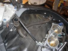
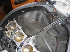
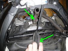
The images below left and middle shows the heat guard rubber with the cranck case
breather hose and the PAIR suction hose sticking up through holes in the rubber.
The image below right shows how the rubber front edge is attached to a hook in
front of the cranck case breather hose.
- Cover the four air intake ports with a clean cloth to keep dirt out.
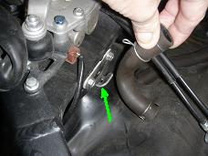
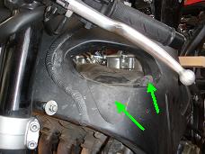
The image below left shows the two attachment points on the right side of the
frame.
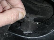
- Pull the small rubber tab out of the rectangular hole in the frame (below middle).
The tip of the rubber sticking out of the hole in the frame has been glued onto the
frame with double adhecive tape.
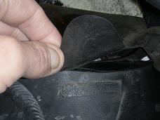
- Release the rubber corner from the double sided adhecive tape and remove the
tape (below right), as we will be using new tape when remounting.
- Release the rubber on the left side of the frame in similar way.
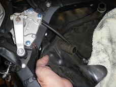
- Release the rubber from the front hook and pull it back over the two hoses (below left).
- Disconnect the cranck case breather hose and tape up the stud, to keep dirt out
(below right).
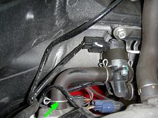
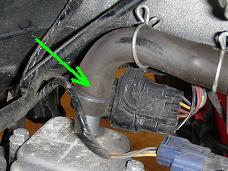
- Release the left side PAIR hose clamp and disconnect hose from the stud on the valve
cover (below left and middle).
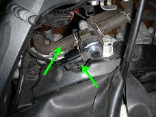
- Disconnect the right PAIR hose in the same way. Tilt the PAIR valve onto its side
and pull it backwards and left (below right).
- Disconnect the 2 pin black connector on the PAIR valve (below right) and remove
the valve with the three hoses still attached.
- Tape up the two studs on the valve cover, to keep dirt out.
5 PAIR Control Solenoid Valve Inspection
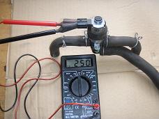
- Connect an Ohm-meter to the two pins on the PAIR valve terminals and measure the
resistance (below left). It shall be in the range 230 - 270 Ohm (the Honda Shop Manual
incorrectly specifies 23 - 27 Ohm!).
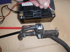
- Check that the valve operates correctly when 12 V is applied to the terminals (below right).
You will hear and feel the valve operate, and you can try to blow air through the long
suction hose, to check that the valve is indeed able to block and unblock the air flow.

6 PAIR Control Solenoid Valve Installation
Installation procedure is same as removal procedure in reversed order and with exceptions as described in the referenced DIY articles and here below.
6.1 Reinstall the PAIR solenoid valve.
6.2 Reconnect the PAIR valve 2 pin black connector.
6.3 Push the harness tab into the rubber holder on the PAIR valve.
6.4 Reposition the front heat guard rubber and hang the front edge on the hook.
6.5 Use new double sided adheceive tape to glue the right and left tips of the heat guard
rubber to the frame (image below).

6.6 Remount the cranck case breather hoose on the valve cover stud.
7 Install the air cleaner housing.
10 Reconnect the Battery.
11 Remount Seat and Side Covers.
Finished.
Front Page - Other DIY Articles
You are invited to participate with review, questions and discussion via this - link to come - thread on www.fireblades.org or this - link to come - thread on www.1000rr.net.
See also:
How to DIY (warnings, tips, tools,
methods, ... etc.)
First Year
with my Fireblade
Superbikes on the Road: BMW S1000RR versus
Honda CBR1000RR Fireblade
Front Page - Other DIY Articles
© Copyright 2012 FireBladerDk. Last updated 2013-02-23