This job is normally done as part of the valve clearance inspection.
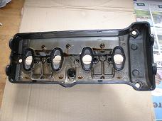 The inside of the valve cover.
This Do It Yourself (DIY) article describes how to remove and reinstall the
cylinder head cover on a 2008 CBR1000RR Honda Fireblade motorcycle.
This job is normally done as part of the
valve clearance inspection.
 The inside of the valve cover.
This is a reasonably easy DIY task. It involves many steps but most of them
are not dificult. The most difficult thing is probably getting the cylinder head cover
manouvered out of the frame and back in during reassembly, because it sits in a very tight
space. Furthermore there are quite a number of parts being removed from the bike,so
take your time and keep track of where you are in the process.
A first timer may spend 6-10 hours on it, an experienced may do it in about 4 hours.
Tools and Parts needed:
Front Page - Other DIY Articles
3.1 Place the bike on the side stand or on a rear wheel lifter.
3.2 Lift the tank.
3.3 Remove the Air Cleaner Housing.
3.4 Remove the PAIR Control Solenoid Valve.
3.5 Remove the Direct Ignition Coils and Spark Plugs.
3.6 Remove the Cylinder Head Cover:
First notice how the clutch cable is routed up past the valve cover on the inside of the frame
(sorry I forgot to take a picture showing this detail). In the following it may prove difficult
- if not down right impossible - for you to get the valve cover out from the frame because the
clutch cable is in the way. In that case simply remove the clutch cable.
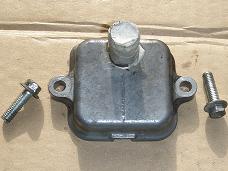
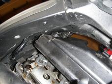
- Unscrew the two bolts on the left PAIR check valve cover and remove the cover (below left
and middle). Removing this cover now makes it possible to get the valve cover out through
the very tight passage in the frame.
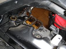
- Remove the four cylinder head cover bolts. There is one on the lets side, one in the middle
and two on the right side. Under each bolt head there is a washer which should also be removed,
either now or later when the valve cover has been removed completely. On the image below middle
the leftmost bolt hole is visible, still with the washer sitting in the hole.
- Release the valve cover from the cylinder head. This may be difficult because the rubber
casket may be binding. I used a rubber mallet and a piece of hard wood to strike gently upwards
on the front edge of the cover. You must be very carefull not to scratch or in any other way
damage the metal, as this might make it difficult to obtain an oil tight seal on reassembly.
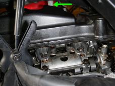
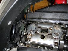
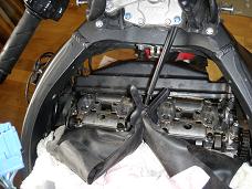
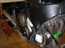
- Carefully lift the cover a few centimeters and ease it forward, so the tube of the right
side PAIR check valve cover passes under the frame (green arrow above right and below). Make
sure the rubber gasket is not stressed in any way.
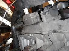
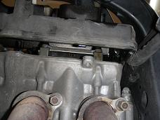
On the images below, the cover is allmost out. There is very little clearance
to the frame when taking the cover out, so be very carefull not to pinch and
damage the rubber gasket on the sharp metal edges.
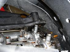
- OBS: It is now time to practice insertion of the
cover a couple of times, so you know exactly how to do it correctly:
The rubber gasket must be kept in correct position, and should not in any way be
squezed on its way in. If this is done incorrectly during final assembly (with
fluent RTV sealant on), the gasket may very likely leak oil through, or one of
the gasket half-circles may suddenly pop out resulting in oil all over the
engine!
- Remove the washers from the valve cover if they are still sitting in
their holes as they shall be replaced with new ones on reassembly (below left).
Be carefull not to scratch the surface of the valve cover.
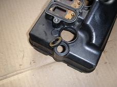
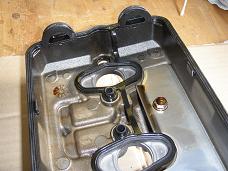
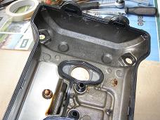
The images below middle and right show the interior of the cover with the rubber
gasket still sitting in place.
- Inspect the gasket for any signs of damage. The gasket is normally reused, but if
it shows any sign of damage it should be replaced with a new one.
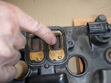
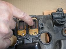
- Inspect the PAIR check valves for wear or damage and check operation as shown
on the images below (middle and right) where a light pressure with a finger opens
the valve a little - barely vissible - on the right image below. It can only open
half a millimeter at the front end. Replace the valves
if necessary.

Installation procedure is same as removal procedure in reversed order and with a few exceptions as described in the referenced DIY articles and here below.
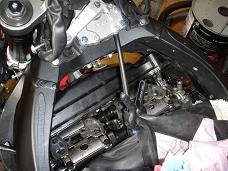
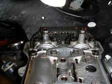
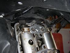
The images below gives an overview of how it looks when ready for reassembly.
Notice that I still had the clutch cable hanging out, and it gave me a great deal of trouble
as it made it almost impossible to mount the valve cover. Next time I will surely remove the
clutch cable during dissasembly.
Also notice that the top edges of the cylinder head still needs some cleaning, as there are
still some of the old RTV sealant sitting on the edges near the half-circle holes. This must
be removed while taking care that nothing falls inside the cylinder head.
8.1 Carefully remove all traces of old RTV sealant from the rubber gasket on the
valve cover (below left). Check that the gasket is in good condition and replace if damaged
or if the rubber seems to be to old and stiff.
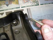
8.2 Apply a small drop (say 3-4 mm in diameter) of RTV sealant in the corners of each
half circle. That will e.g. be just below the end of the twezer in the above image.
8.3 Insert and carefully allign the valve cover before it is lowered down into final position. When lowered the four cylinder head cover bolts must immediately be mounted using new washers. Tighten to 10 Nm (1.0 kgfm, 7 lbfft).
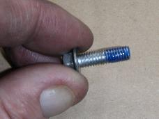
8.4 Install the pair check valve covers using locktight blue (standard). Be sure to clean old locktite from the bolts first, using e.g. a steel brush.
8.5 Install/reposition the clutch cable to the correct position.
8.6 Install the spark plugs and ignition coils.
8.7 Install the PAIR Control Solenoid Valve.
9 Install the air cleaner housing.
12 Reconnect the Battery.
13 Remount Seat and Side Covers.
Finished.
© Copyright 2013 FireBladerDk 2013-01-20.